
 on
the Drawing Toolbar to open the Draw Area Loads Dialog
on
the Drawing Toolbar to open the Draw Area Loads DialogThis section discusses the various Load Types that are available for applying loads to a model.
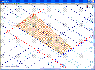
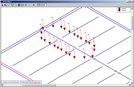
Area Loads that are applied to a floor are automatically attributed to the nearest members that support that area. See Loads – Attribution for more information. This attribution gives you the ability to model all the loading effects on a floor without having to calculate all the loads yourself. The area loads can be uniform or tapered and the loads may be distributed based on one-way or two-way action depending on the deck or slab that supports them.
Note:
To apply area loads click on
the Drawing Toolbar to open the Draw Area Loads Dialog
For a Tapered Area Load, enter in the base magnitude, peak magnitude, and load category of the load. Apply the tapered area load by clicking on the grid or existing point locations. The Base Magnitude of the tapered load is magnitude of the load between the first two points drawn when defining the load. The Peak Magnitude of the tapered load is the magnitude of the load at the third or fourth point entered.
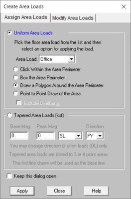
To Apply Area Loads
 on the RISA Toolbar to open a new view
and click
on the RISA Toolbar to open a new view
and click  to turn on the Drawing
Toolbar if it is not already displayed. button on the Drawing Toolbar and define
the load in the Draw Area Loads Dialog.
to turn on the Drawing
Toolbar if it is not already displayed. button on the Drawing Toolbar and define
the load in the Draw Area Loads Dialog.Note:
 button.
The Area Load Definitions Spreadsheet defines the uniform area
load magnitudes and may be accessed by selecting Loads ![]() Area Load Definitions from the Spreadsheets
Menu. While the load magnitudes are defined in this spreadsheet,
they can only be assigned graphically.
Area Load Definitions from the Spreadsheets
Menu. While the load magnitudes are defined in this spreadsheet,
they can only be assigned graphically.
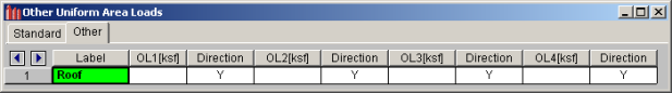
When you open this spreadsheet you are presented with two tabs, Standard and Other.
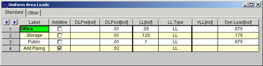
The first column is the area load Label. This label is a description for your own use.
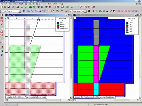
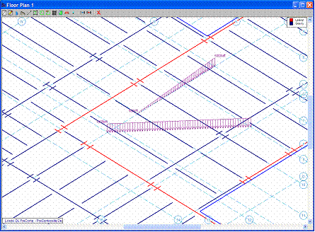
A check in the second column indicates that the load is additive. An additive load gets added to the area load defined directly beneath it. For example, loads such as piping or HVAC are sometimes applied in addition to the office or storage loads defined for that area. In the following diagram the additive piping load (Add Piping) is added directly to the office, storage, and public loads that were drawn beneath it.
For additional advice on this topic, please see the RISA Tips & Tricks website: www.risa.com/post/support. Type in Search keywords: Additive Area Loads.
The remaining columns define the magnitude of the load for each load case. The last two columns are the Vibration Live Load and the Dynamic Load. The Vibration Live Load will used when checking floor vibration per AISC Design Guide 11. See Vibrations for more information. The dynamic mass will be included as part of the defined mass when interfacing with RISA-3D. See RISA-3D Integration for more information.
Other loads can also be applied graphically, see Drawing Area Loads. Other loads can be defined in any direction, see Load Direction. On the Other tab of the Area Load Definitions Spreadsheet the first column contains the load magnitude while the second contains the load direction.
The Tapered Area Load Spreadsheet records the uniform
area loads to be attributed to the members and may be accessed by selecting
Loads ![]() Tapered Area Loads on the Spreadsheets
Menu. You may define Tapered Area Loads graphically or by
using the spreadsheets. See Drawing
Area Loads to learn how to draw these loads graphically.
Tapered Area Loads on the Spreadsheets
Menu. You may define Tapered Area Loads graphically or by
using the spreadsheets. See Drawing
Area Loads to learn how to draw these loads graphically.
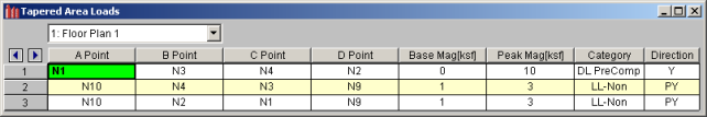
The spreadsheet contains the points that define the area load, the base magnitude and the peak magnitude. The drop down list at the top of the spreadsheet allows you to toggle between floors.
Note:
Deck Loads consist of the deck self weight, construction dead load, and construction live loads and are all specified from within the Deck Definitions Spreadsheet. Note that these are different from the area loads defined in the Area Load Definitions Spreadsheet as these loads are specifically linked to the type of deck construction. For more information on this topic refer to Deck Properties - Loads.
Note:
The Area Load Query dialog is activated by clicking on the icon shown above and then clicking on any location on the floor. The purpose of this dialog is to allow the user to investigate the loading at any point on their floor.
This dialog will display the loading associated with a particular Load Combination. It lets you see how the various default loading interacts with defined area loads, tapered area loads, and deck loading.
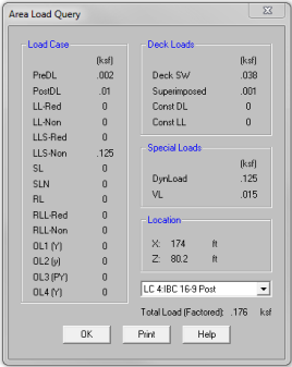
The Load Combination drop down menu allows the users to select whichever load combination they are interested in.
The Location reports the point on the floor for which the loading is being reported.
The Load Case section of the dialog will display loading any Area Load Definitions that will apply at the selected location for that load combination. This also includes and Tapered Area Loads that are applied in that location.
Note:
The Deck Loads section refers to loading associated with the deck defined at that location.
The Special Loads section is NOT associated with the particular load combination because these "special" loads are used for vibration or seismic load calculations and are never themselves included in a load combination.
The Total Load (Factored) adds up all the forms of area loading applied in the specified load combination. In includes any load factors applied in that load combination. This, obviously, does not include other forms of loading such as point loads, line load, column or wall reactions from above. Nor does it include any reduction of Live Loading based on tributary area.
Line Loads are linear loads that can be placed anywhere on a  button on the Drawing Toolbar.
To draw line loads graphically, click the button on the Drawing Toolbar to open the Draw
Line Loads Dialog. Enter the start magnitude and the end
magnitude
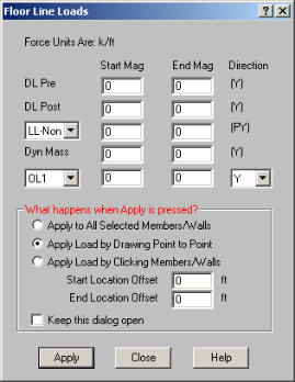
To Apply Line Loads
on the RISA Toolbar to open a new view
and click to turn on the Drawing
Toolbar if it is not already displayed.Note
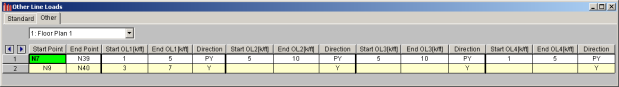
button.The Line Loads Spreadsheet records the line loads on ![]() Line Loads
on the Spreadsheets Menu.
Line Loads
on the Spreadsheets Menu.
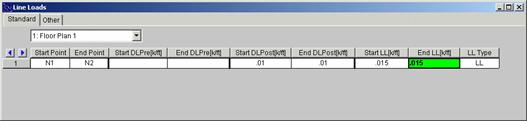
The remaining columns contain the Start Magnitude and End Magnitude of each line load for the Standard Load cases.
On the Other tab, the columns contain the Start and End Points and the Start and End Magnitudes of each line load for the Other Load cases as well as the load direction
Point Loads are concentrated loads and may be placed anywhere on a  button on the Drawing Toolbar.
To draw point loads graphically, click the  button on
the Drawing Toolbar to open the Draw Point Loads Dialog. Enter the magnitude of the point load
button on
the Drawing Toolbar to open the Draw Point Loads Dialog. Enter the magnitude of the point load
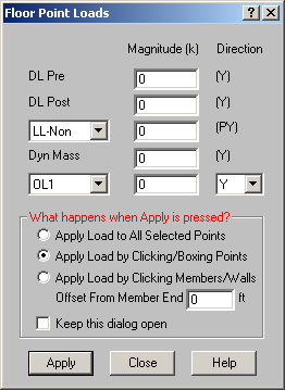
To Apply Point Loads
on the RISA Toolbar to open a new view
and click to turn on the Drawing
Toolbar if it is not already displayed. button on the Drawing Toolbar and
define the load in the Draw Point Loads Dialog.You can apply the point load by clicking Apply and clicking or boxing grid or point locations in the model view.
Note
button.The Point Loads Spreadsheet records the point loads on ![]() Point Loads
on the Spreadsheets Menu.
Point Loads
on the Spreadsheets Menu.
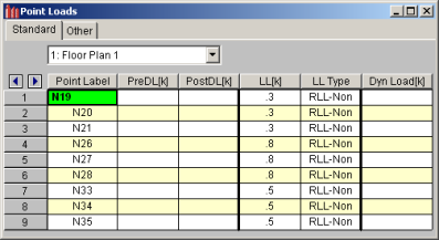
In either the Standard or Other tabs, the first column contains the point that receives the load. The next columns contain the magnitudes of the load respectively for each load case. The pull down list at the top of the spreadsheet allows you to toggle between floors.